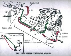
Lt1 Coolant Flow Diagram
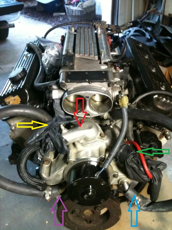
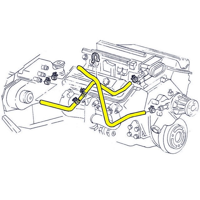
The two smaller hoses are for the heater right next to it is the inlet where the tstat is located and the outlet is at the top where the cooler also connects inline Corvette Lt1 Coolant Flow Diagram. The LT1 is completely different since it uses reverse flow cooling.
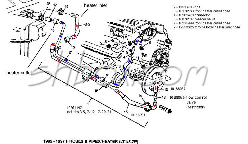
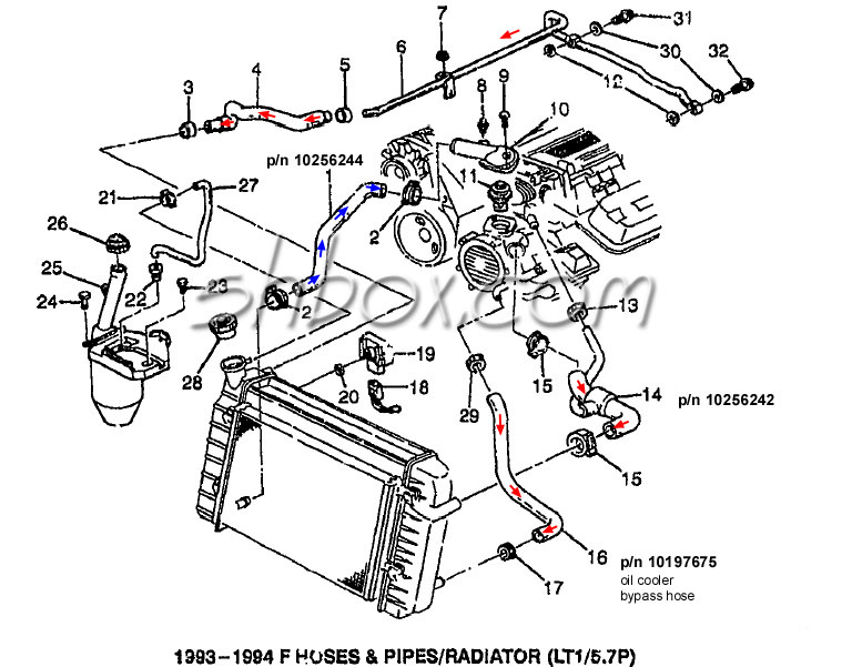
Lt1 Swap Radiator Hose Questions With Diagram For Future Reference Third Generation F Body Message Boards
LT1 Reverse Flow Cooling SystemOn my 1995 Chevy Camaro Z28 With the LT1Some basic info about the LT1 Reverse Flow Cooling SystemAlsoLT1 uses different head.
Lt1 coolant flow diagram. I think the reason the shop manual recommends draining some of the coolant before removing the intake on the LT1 is because coolant does flow through the throttle body in the stock set up. Engine Coolant Flow Diagram. Conventional cooling system design also allows isolated engine hot spots to occur which lead to the generation of steam pockets and coolant foaming.
Lt1 reverse flow cooling system on my 1995 chevy camaro z28 with the lt1 some basic info about the lt1 reverse flow cooling. The direction of coolant flow is not. There are three sensors in the LT1 Cooling system.
Chevy reversed the flow direction in the LT1-LT4 engines to direct the cooling system can easily over come. The Chevrolet LT1 57L V8 engine that was produced from 1992 to 1997 has some significant differences compared to the previous small block Chevy it replaced and the third generation LS1 small block that later replaced it. LT1 POWER MODULE WIRING DIAGRAM AND INSRUCTIONS Thank you for purchasing our product.
The thermostat is on the suction side of the water pump unlike a traditional V8. The direction of coolant flow is not. In GM introduced the LT1 engine a revolutionary new CI small block to be used in all its rear wheel drive vehicles.
Lt1 reverse flow cooling system on my 1995 chevy camaro z28 with the lt1 some basic info about the lt1 reverse flow cooling system. Coolant which is full of air and foam reduces cooling system performance and can even lead to engine overheating. The incoming coolant first encounters the thermostat which now acts both on the inlet and outlet sides of the system.
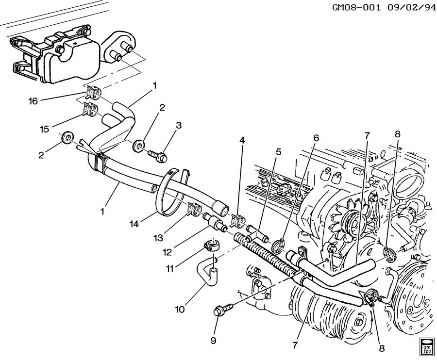
73 87 chevy gmc trucks coolant flow question. From the cylinder heads the coolant is then forced to the thermostat. Refer to items 4 and 5 in the diagram posted above those are the hoses that connect to the t-body.
The LT1 is completely different since it uses reverse flow cooling. Water exits the radiator from the passenger side tank if its a crossflow bottom tank if its a downflow and goes to the thermostat housing. Depending on the engine coolant temperature cold coolant from the radiator is.
Depending on the engine coolant temperature cold coolant from the radiator. Cap still off turn on the engine and let it idle. LT1 Coolant Flow.
Oct 19 LT1-LT4 Modifications - Waterpump and coolant flow with pics - Guys I am trying in the middle which incorporates into the hose routing. This sensor only sends a signal to the light on the instrument panel to illuminate the low coolant indicator lamp. The 94 97 lt1 and lt4 intake manifolds appear the same from above all lt4 intakes are powder coated red from factory but the difference is in the intake ports.
In 1992 GM introduced the LT1 engine a revolutionary new 350 CI small block to be used in all its rear wheel drive vehicles. The incoming coolant first encounters the thermostat which now acts both on the inlet and outlet sides of the system. The thermostat provides control for your engines warm-up period.
5 Mar 22 2009 Edited On a Caprice is goes to the expansion coolant tank. All coolant flow paths roughly equal in the crappy diagram below the blue. Speaking of the cooling systems sensors.
F-body technical specifications part locations part numbers how-to guides diagrams. Begin by training the water from your 1999 chevy tahoe cooling system. The B-body and F-body used different cooling systems.
B-body had the pressure cap on the take. Coolant Flow Radiator And Engine Block Below is an explanation of this systems operation The Thermostat Just like your body needs to warm up when you begin to exercise your cars engine needs to warm up when it starts its exercise. Below is a picture of where.
The flow of coolant will either be stopped at the thermostat until the engine is warmed or it will flow through the thermostat and into the radiator where it is cooled and the coolant cycle is. Engine Coolant Level Sensor. Best way i know how and was showed.
Coolant flow radiator and engine block thecarguys coolant flow radiator and engine block below is an explanation of this system s operation the thermostat just like your body needs to warm up when you lt1 engine coolant flow diagram imageresizertool lt1 engine coolant flow diagram as well as hose set engine radiator coolant heater lt1 lt4 engines 1995 1996 further. Watch the coolant level go down as it does fill to the top of the reservoir just below that little overflow pipe in the radiator neck. Chevy reversed the flow direction in the LT1-LT4 engines to direct the cooling system can easily over come.
It was a 34 hole or so that I screwed an adapter fitting into to allow me to connect the 316 or so hose to. All of these engines from 1992 through 1997 use a reverse flow water pump that is driven directly off the camshaft. You your self a favor and do the tb-bypass.
- 02032017 This is a brief and concise guide to those who are interested in installing the new generation of LT crate. Radiator Mounting Exploded View. My problem is I changed radiators this one has plastic tanks the fitting is now a molded plastic connection.
This really has nothing to do with the reverse flow cooling system they just put the thermostat in a different place. LT1 Coolant Flow. Lt1 engine diagram.
Close both bleed screws. Open the bleed screw closest to the. The LT1 is completely different since it uses reverse flow cooling.
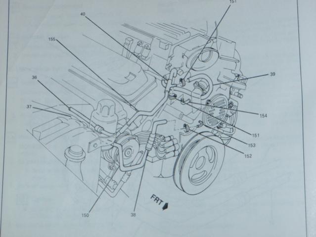
Hacksters daily driver lq4 and tLT1 engine JTR radiator. Routing LT1 coolantsteam lines from back of heads. I am working on a camaro with lt1 tonight i willsee which hose goes to discharge from The thermostat is on.
4th Gen LT1 F-Body Technical Aids Diagrams Drawings Exploded Views For 1995 F-body unless otherwise noted. If the coolant is already to the top of the radiator neck then skip this step. We do everything we can to provide you with the most current and up to date diagrams.
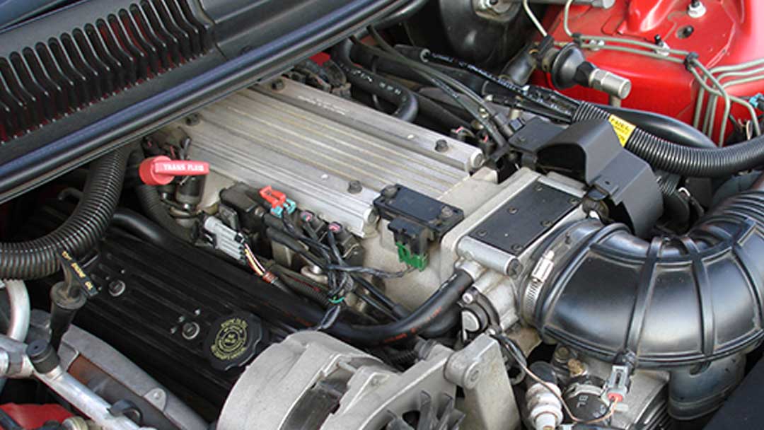
The most obvious difference that distinguishes the LT1 from these other engines is the front-mounted Opti-Spark ignition system. Basically the 2 hoses that go to the TB skip the TB and join the hose from the tank to the line that runs to. All coolant flow paths roughly equal in the crappy diagram below the blueMay 30 Reverse flow cooling is THE KEY to the Generation II LT1s increased power durability and reliability over the.
1995 Lt1 Engine Cooling Line Routing Camaroz28 Com Message Board

1993 1994 Corvette Engine Cooling System Rubber Hose Set Lt1 Corvetteparts Com
Lt1 Coolant Hose Diagram Shefalitayal
Lt1 Cooling System Diagram Shefalitayal
How The General Motors Lt1 Reverse Flow Cooling System Operates
Need Help With Lt1 Heater Hoses Third Generation F Body Message Boards
Lt1 In Chevy Truck Camaro Forums At Z28 Com
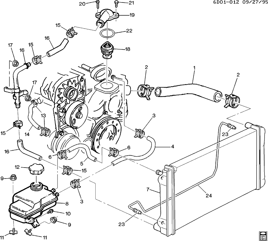
Diagram Lt Vats Wiring Diagram 1 Mogar Infinityagespa It
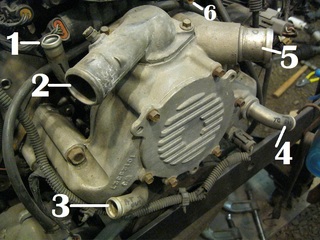
Help Id Lt 1 Water Pump Ports Please Corvetteforum Chevrolet Corvette Forum Discussion

Diagram Lt1 Coolant Diagram Full Version Hd Quality Coolant Diagram Diagrammagroup Reverbfestival It
Cooling System Diagram Camaro Forums Chevy Camaro Enthusiast Forum
1992 Corvette Engine Cooling System Rubber Hose Set Lt1 Corvetteparts Com
4th Gen Lt1 F Body Tech Aids Drawings Exploded Views
Corvette Lt 1 Water Pump Inlet Outlet Id Hot Rod Forum

Heater Control Valve Corvetteforum Chevrolet Corvette Forum Discussion
Lt1 Steam Pipe Question Third Generation F Body Message Boards
Steam Line
Engine Water Pumps Grumpys Performance Garage
Lt1 In Mustang


Post a Comment for "Lt1 Coolant Flow Diagram"